


LCD Module 5V Yellow-Green Backlight
Regular price $14.56 Sale price $10.40SPECIFICATIONS
Brand Name: NoEnName_Null
Choice: yes
Display Mode: 0
Hign-concerned Chemical: None
Origin: Mainland China
Resolution: 16*2
is_customized: Yes
semi_Choice: yes
Glass Size
Blue Background with White Characters
Standard 16X2 LCD Character Module (Backlight/Blue Screen)
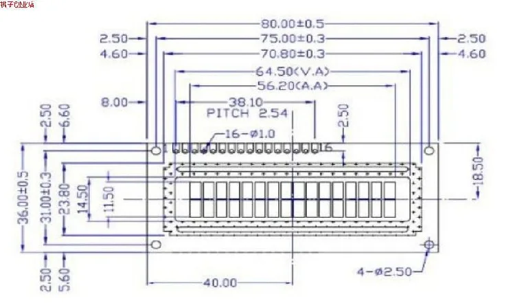
1602 uses a standard 16-pin interface, including:
Foot: VSS is Ground Power Supply
Pin 2: VDD connects to 5V positive power supply
3rd pin: V0 is LCD display contrast adjustment terminal.When connected to positive power, contrast is weak; when connected to ground power, contrast is high.Excessive contrast can produce ghosting.During use, you can adjust contrast with a 10K potentiometer
Pin 4: RS is register selection, selects data register when high level, selects instruction register when low level.
Pin 5: R/is read-write signal line, it performs read operations when high level and write operations when low level.When RS and RW are both low levels, you can write commands or display addresses;when RS is low and RW is high, you can read busy signal;when RS is high and RW is low, you can write data.
Pin 6: E terminal is enable terminal.When E terminal changes from high level to low level, LCD module executes commands.
7th to 14th pins: D0 to D7 are 8-bit bidirectional data lines.
5 pins: Backlight power supply positive terminal
6 pins: Backlight power supply negative terminal
character generation (CGROM) inside 1602 LCD module has stored 160 different character graphics, as shown in Table 1.These characters include: Arabic numerals, uppercase and lowercase English letters, commonly used, and Japanese kana.Each character has a fixed code; example, code uppercase English letter 'A' is01000001B (41H), when displayed, module shows character graphics at address 41H, allowing us to see letter 'A'.
following is program displaying letter 'A' at position of second row character in LCD module: ORG 0000H
RS EQU P3.; Determine specific hardware connection method
RW EQU P3.6; Determine specific hardware connection method
E EQU P3.5; Determine specific hardware connection method
MOV P1,00000001B; screen and reset cursor
ACALL ENABLE; Call write command subroutine
MOV P1,00111000B; Set display mode: 8-bit 2-line 5x7
ACALL ENABLE; Call write command subroutine
MOV P1,00001111B; Monitor on, cursor on, cursor allowed to flicker
ACALL ENABLE; Call write command subroutine
MOV P1,00000110B; Text does not move, cursor automatically moves right
ACALL ENABLE; Call write command subroutine
MOV P1,0C0H; Write starting address display (second line position)
ACALL ENABLE; Call write command subroutine
MOV P1,01000001Code letter B; code letter A
SETB RS; RS=1.
CLR RW ;RW=0 ;Prepare to write data
CLR E.... ;E=0 ;Execute display command
ACALL DELAY; Determine if LCD module is busy?
SETB E....; E=1; Display completed, program stopped
AJMP $
ENABLE:
CLR RS; subroutine writing control commands
CLR RW
CLR E
ACALL DELAY
SETB E
RET...
DELAY:
MOV P1,0FFH; Subroutine to determine if LCD display is busy
CLR RS
SETB RW
CLR E
NOP
SETB E
JB P1., DELAY; if P1.is high level, it means busy and will wait in a loop
RET
END
program initially initializes LCD module functions and sets display format.Note that when displaying characters, cursor moves automatically to right without manual intervention.Each you enter a command, first call subroutine DELAY to check if LCD module is busy, then enter address 0C0H display position, and finally enter code 41H character A to be displayed.
SMC1602A (16*2) Analog Port Line Connection Method
Connection Diagram:
---------------------------------------------------
LCM-----51 LCM-----51 LCM------51
------------------------------------------------
DB0-----P1.0 DB4-----P1.4 RW-------P2.0
DB1-----P1.1 DB5-----P1.5 RS-------P2.1
DB2-----P1.2 DB6-----P1.6 E--------P2.2
DB3-----P1.3 DB7-----P1.VLCD connected to 1K resistor to GND
---------------------------------------------------
[Note: AT89S52 uses a 12M oscillator]
=============================================================*/
define LCM_RW P2_0 //Define pin
define LCM_RS P2_1
define LCM_E P2_2
define LCM_Data P1
define Busy 0x80 // Used to detect Busy in LCM status word
#i nclude
void WriteDataLCM(unsigned char WDLCM);
void WriteCommandLCM(unsigned char WCLCM,BuysC);
unsigned char ReadDataLCM(void);
unsigned char ReadStatusLCM(void);
void LCMInit(void);
void DisplayOneChar(unsigned char X, unsigned char Y, unsigned char DData);
void DisplayListChar(unsigned char X, unsigned char Y, unsigned char code *Data);
void Delay5Ms(void);
void Delay400Ms(void);
unsigned char code uctech[] = {uctech
unsigned char code net[] = {uctech.icpcn.com
void main(void)
{
Delay400Ms(); //Start waiting until LCM enters working state
LCMInit(); // LCM initialization
Delay5Ms(); //Delay a moment (not necessary)
DisplayListChar(0, 5, uctech);
DisplayListChar(0, 0, net);
ReadDataLCM(); // statement is meaningless
while(1);
}
//Write Data
void WriteDataLCM(unsigned char WDLCM)
{
ReadStatusLCM(); // Detection Busy
LCM_Data = WDLCM;
LCM_RS = 1;
LCM_RW = 0;
LCM_E = 0; // If oscillator speed is too high, you can add a small delay here
LCM_E = 0; //Delay
LCM_E = 1;
}
Write instructions
void WriteCommandLCM(unsigned char WCLCM,BuysC) // BuysC sets busy detection to ignore when 0
{
if (BuysC) ReadStatusLCM(); //Detect Busy Status as Needed
LCM_Data = WCLCM;
LCM_RS = 0;
LCM_RW = 0;
LCM_E = 0;
LCM_E = 0;
LCM_E = 1;
}
Read data
unsigned char ReadDataLCM(void)
{
LCM_RS = 1;
LCM_RW = 1;
LCM_E = 0;
LCM_E = 0;
LCM_E = 1;
return(LCM_Data);
}
//Read Status
unsigned char ReadStatusLCM(void)
{
LCM Data = 0xFF;
LCM_RS = 0;
LCM_RW = 1;
LCM_E = 0;
LCM_E = 0;
LCM_E = 1;
While (Lcm_data & Busy); // Detect Busy Signals
return(LCM_Data);
}
void LCMInit(void) // LCM initialization
{
LCM_Data = 0;
Writecomandlcm (0X38,0); // Set Display Mode Three Times without Detecting Busy Signals.
Delay5Ms();
WriteCommandLCM(0x38,0);
Delay5Ms();
WriteCommandLCM(0x38,0);
Delay5Ms();
WriteCommandLCM(0x38,1); // Display mode setting, start requesting busy signal detection each
WriteCommandLCM(0x08,1); //Turn off display
WriteCommandLCM(0x01,1); //Display Screen
WriteCommandLCM(0x06,1); // Display cursor movement settings
WriteCommandLCM(0x0C,1); // Display On and Cursor Settings
}
Display a character at specified position
void DisplayOneChar(unsigned char X, unsigned char Y, unsigned char DData)
{
Y equals 0 times x1.
X & = 0xF; // Limit X Cannot Be Greater than 15 and Y Cannot Be Greater than 1.
If (Y) X = 0X40; // When Second Row Is to Be Displayed, Address Code 0X40;
X = 0X80; // Calculate Instruction Code
Writecomandlcm (X, 0); // No Busy Signal Is Detected Here, and Address Code Is Sent.
WriteDataLCM(DData);
}
//Display a string of characters at specified position
void DisplayListChar(unsigned char X, unsigned char Y, unsigned char code *Data)
{
unsigned char ListLength;
ListLength = 0;
Y equals 0 times x1.
X & = 0xF; // Limit X Cannot Be Greater than 15 and Y Cannot Be Greater than 1.
While (Ddata [Listlength]>0X20) // Exit If End of String Is Reached
{
If (X)<= 0xF) // X Coordinate Should Be Less than 0xF
{
DisplayOneChar(X, Y, Data[ListLength]); // Display a single character
ListLength ;
X ;
}
}
}
5ms Delay
void Delay5Ms(void)
{
unsigned int TempCyc = 5552;
while(TempCyc--);
}
400ms Delay
void Delay400Ms(void)
{
unsigned char TempCycA = 5;
unsigned int TempCycB;
while(TempCycA--)
{
TempCycB=7269;
while(TempCycB--);
};
above Procedures Are Reference Only! !